Biomedical devices & simulation · 2024
ExoventQ: a low-cost portable negative-pressure ventilator
A student-led respiratory support prototype with continuous and cyclic negative-pressure modes, closed-loop pressure control and safety alarms.
BSc Electrical Engineering senior design project, 2020–2021 · Qatar University QUST-1-CENG-2023-796 · Prince Sattam Bin Abdulaziz University project PSAU/2024/R/1445
Approach
Can a portable negative-pressure ventilator be built from affordable, readily available components?
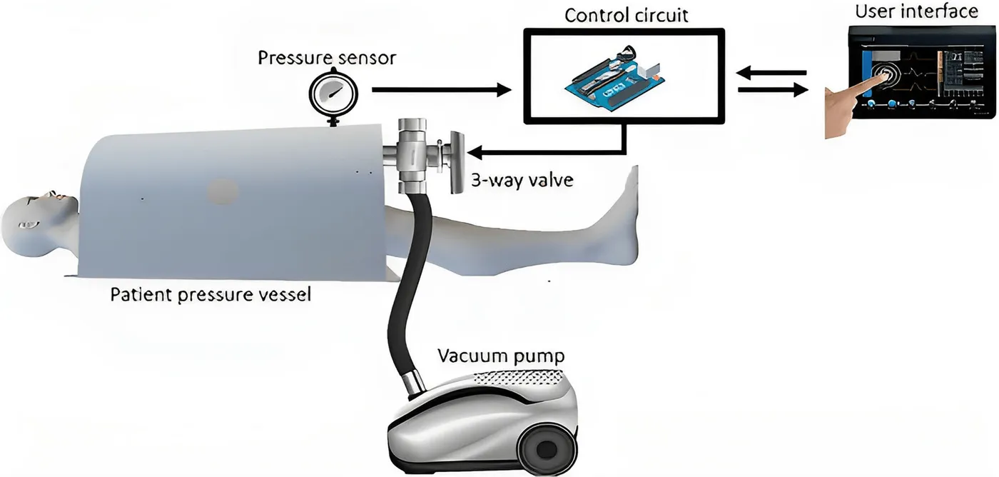
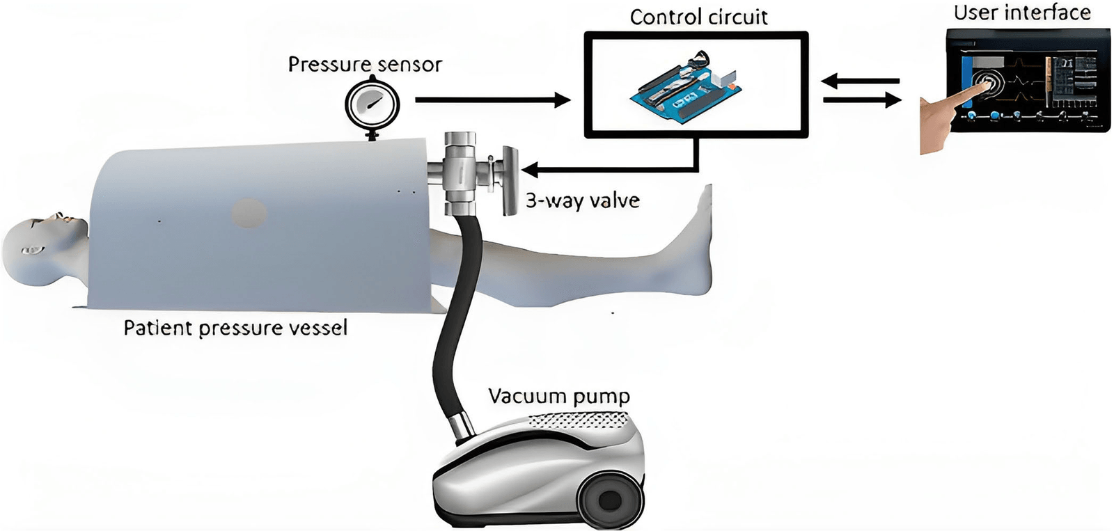
The COVID-19 pandemic exposed global shortages of mechanical ventilators. ExoventQ began as a final-year engineering project to explore a lower-cost alternative that applies negative pressure around the chest instead of delivering positive pressure through the airway. The team designed the pressure vessel, pumping system, control electronics and clinician interface, then tested the integrated prototype.
- Design the pressure vessel
- Build pumping and control
- Test modes and safety
Designing and building the pressure vessel
IEEE Access · 2024
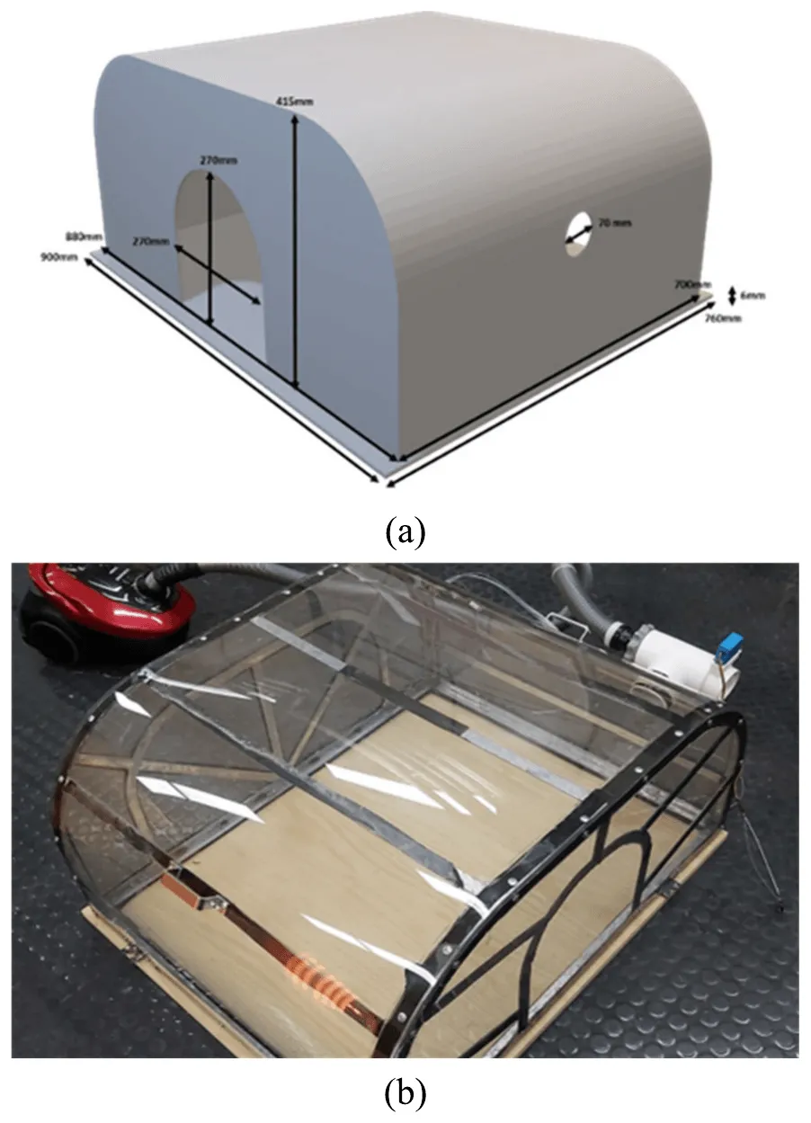
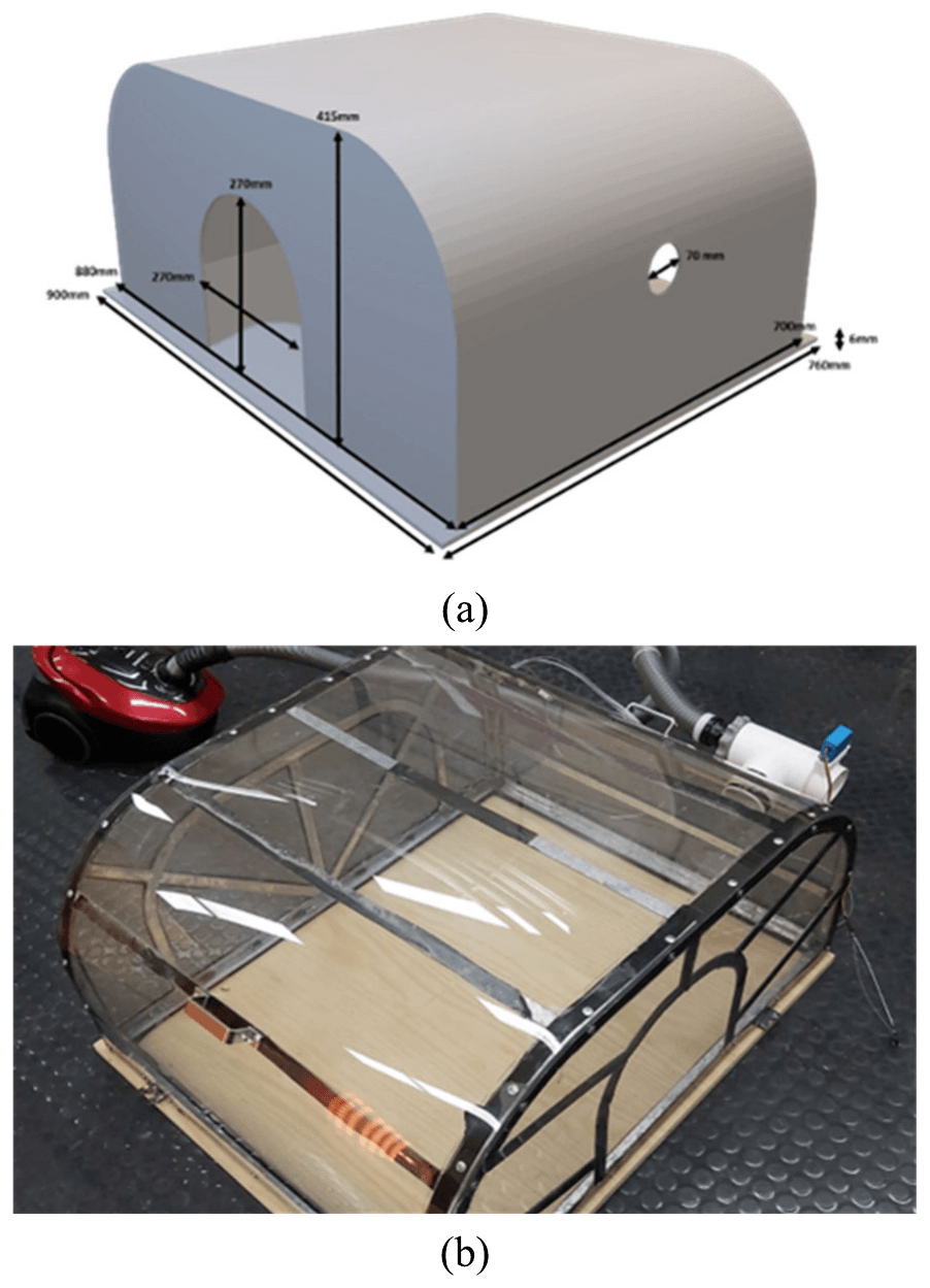
The team first built a wooden prismatic vessel to test operation and sealing, then developed a transparent polycarbonate vessel for the final prototype. ANSYS stress analysis compared semi-cylindrical and rectangular designs and identified a squircle-faced semi-cylinder as the most suitable shape for limiting structural failure.
Polycarbonate was chosen over acrylic because acrylic is more likely to crack during drilling or impact. Neoprene neck and torso seals were selected over latex for their flexibility and lower allergy risk, and the squircle shape avoids tilting the suction tube and valve.
- Vessel vacuum design limit
- 50 mbar
- Polycarbonate wall thickness
- 3 mm
- Adult male design range
- 75–90 kg
| Wooden test vessel | Polycarbonate vessel | |
|---|---|---|
| Length | 0.90 m | 0.90 m |
| Width | 0.64 m | 0.76 m |
| Height | 0.415 m | 0.415 m |
| Main wall | 12 mm plywood | 3 mm polycarbonate |
| Support | Battens and 25 mm girder | Galvanised steel frame |
Generating and controlling negative pressure
IEEE Access · 2024
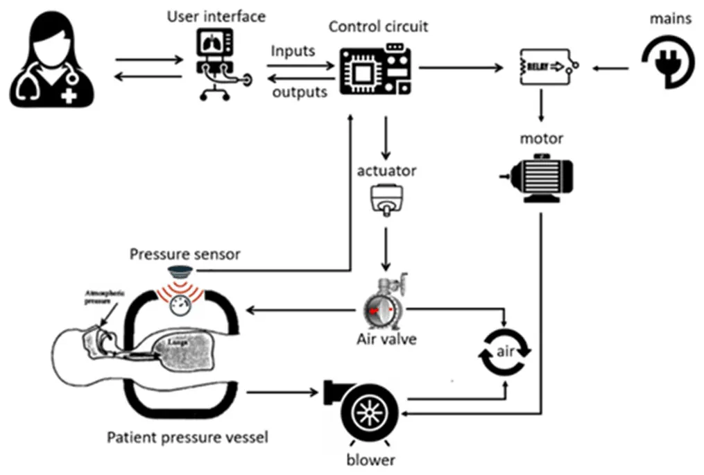
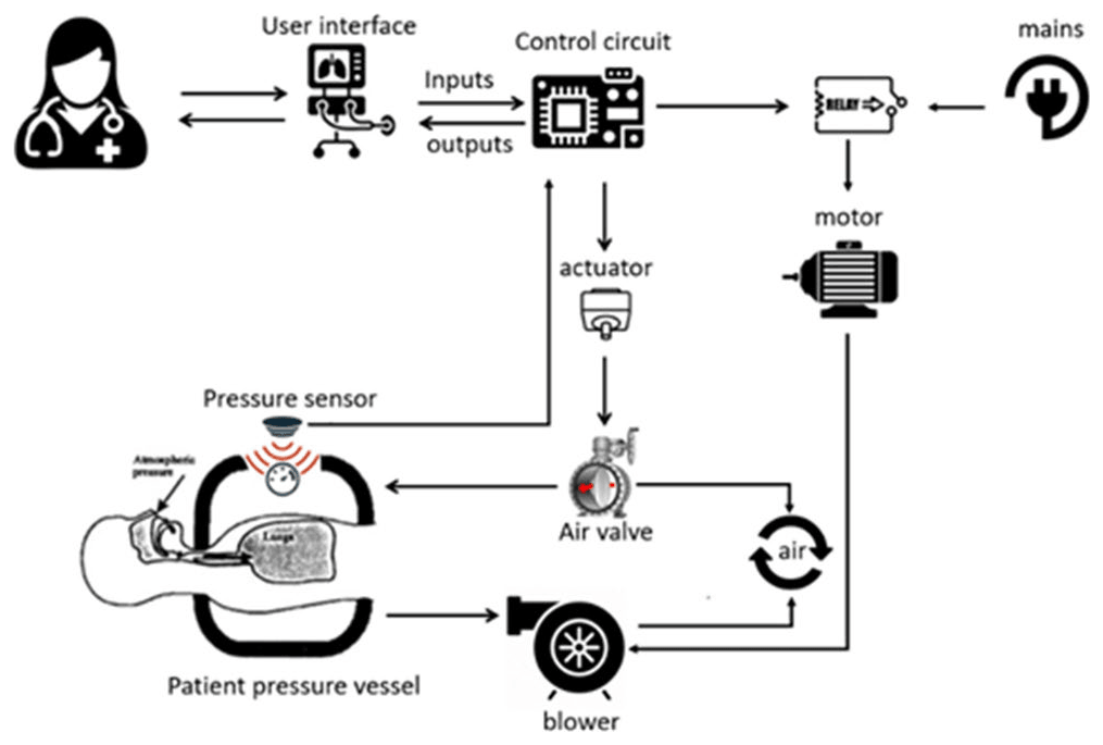
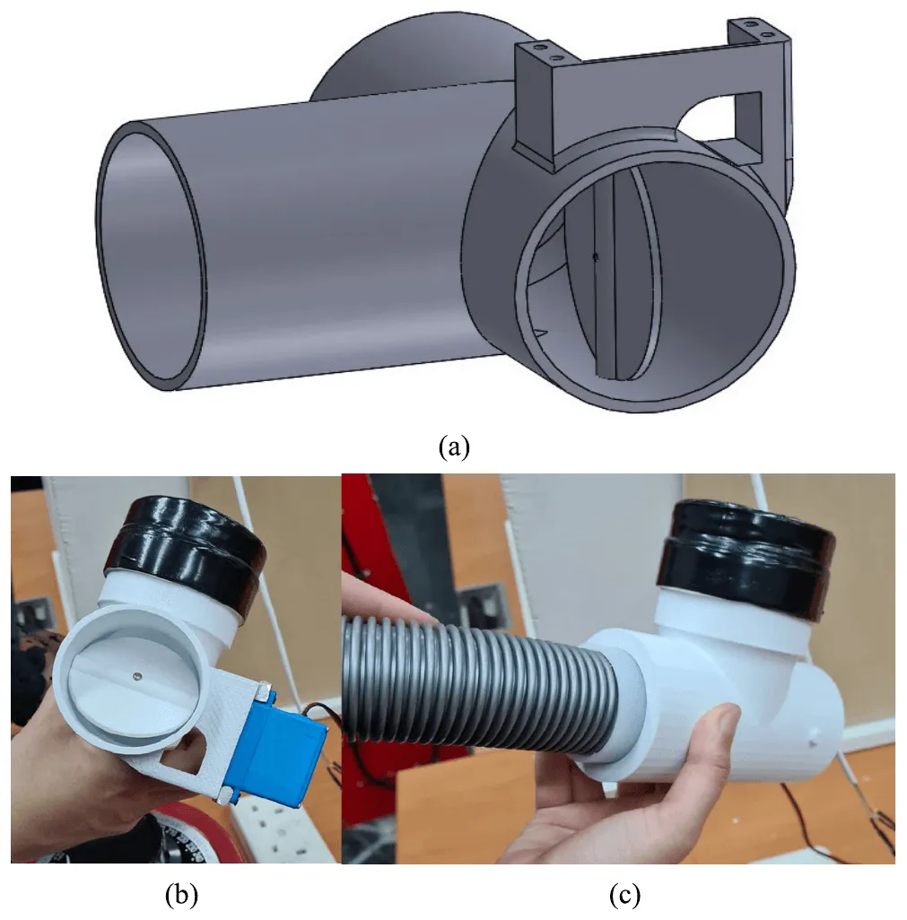
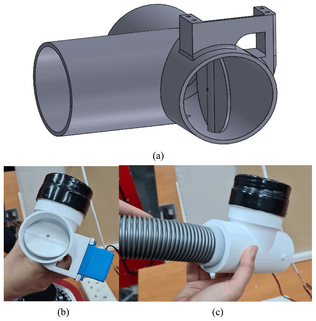
A 200 W vacuum-cleaner motor-blower provided suction, with a maximum vacuum of 15 kPa and airflow of about 13 L/s. A 3D-printed three-way butterfly valve, moved by a servo motor, regulated the air drawn from the vessel.
An Arduino Uno read a pressure sensor checked against a 2 m water manometer and adjusted the valve whenever vessel pressure moved more than 0.5 cmH₂O from its target. A DHT22 sensor monitored temperature, and a Raspberry Pi touchscreen provided the settings, readings and live pressure waveform.
- Pressure correction threshold
- ±0.5 cmH₂O
- Maximum pump vacuum
- 15 kPa
- Pump airflow
- ~13 L/s
| Range | |
|---|---|
| Inspiration pressure | 15–35 cmH₂O |
| Expiration pressure | 0–15 cmH₂O |
| Respiratory rate | 10–30 breaths per minute |
| Inspiration-to-expiration ratio | 1:1 to 1:4 |
| Continuous negative pressure | 5–15 mbar vacuum |
Testing ventilation modes and safety features
IEEE Access · 2024
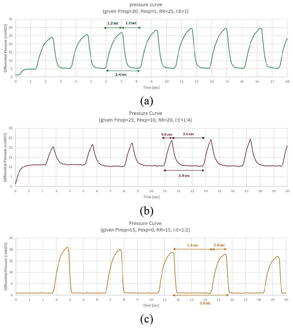
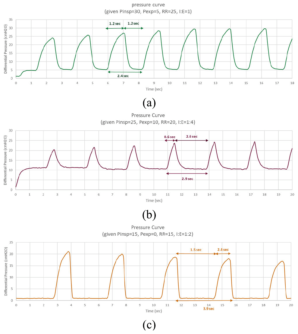
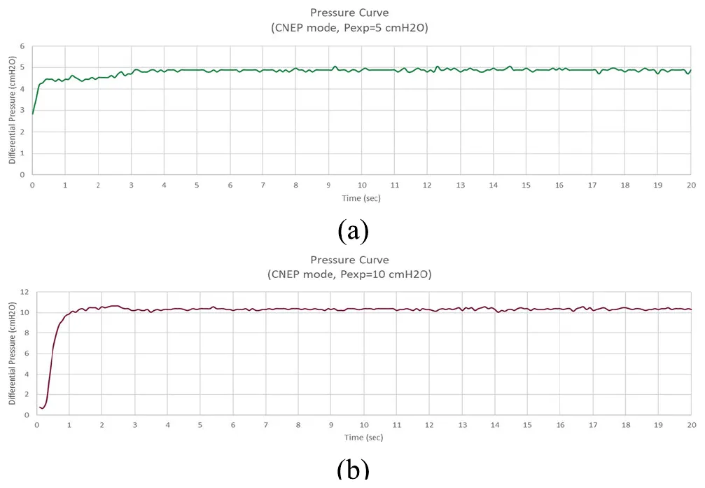
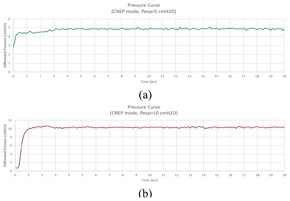
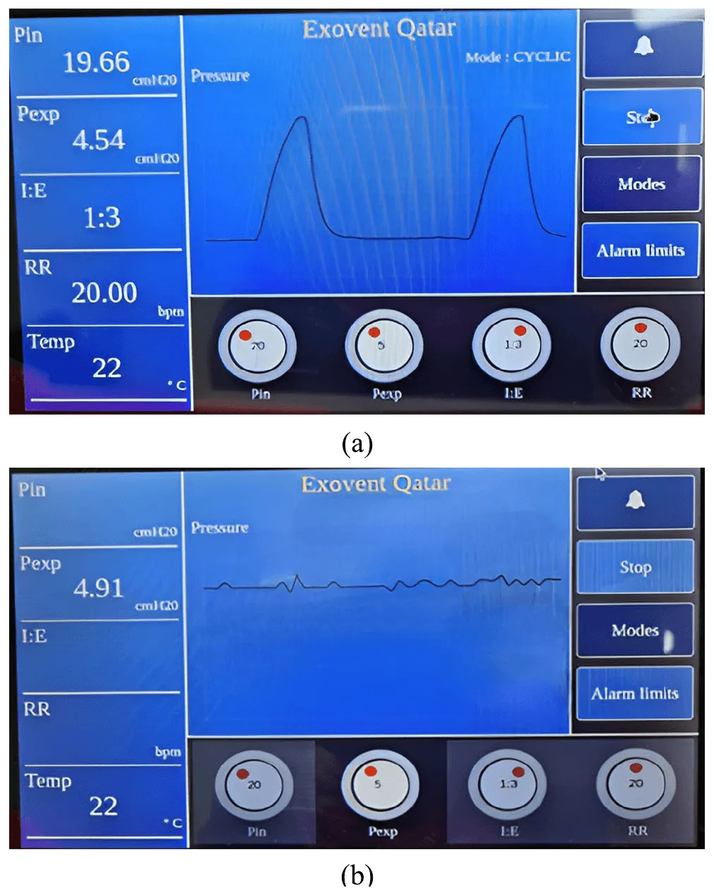
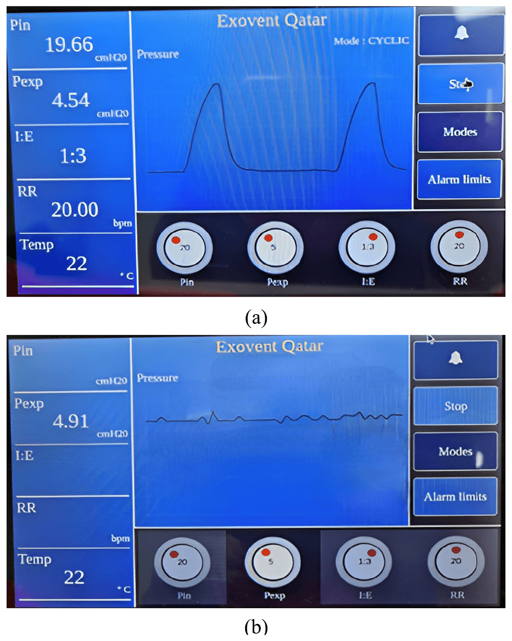
The prototype was tested in cyclic negative-pressure ventilation and continuous negative extrathoracic pressure modes. Pressure curves were recorded while changing the target pressures, respiratory rate and inspiration-to-expiration ratio, and the full system was then checked through the touchscreen interface.
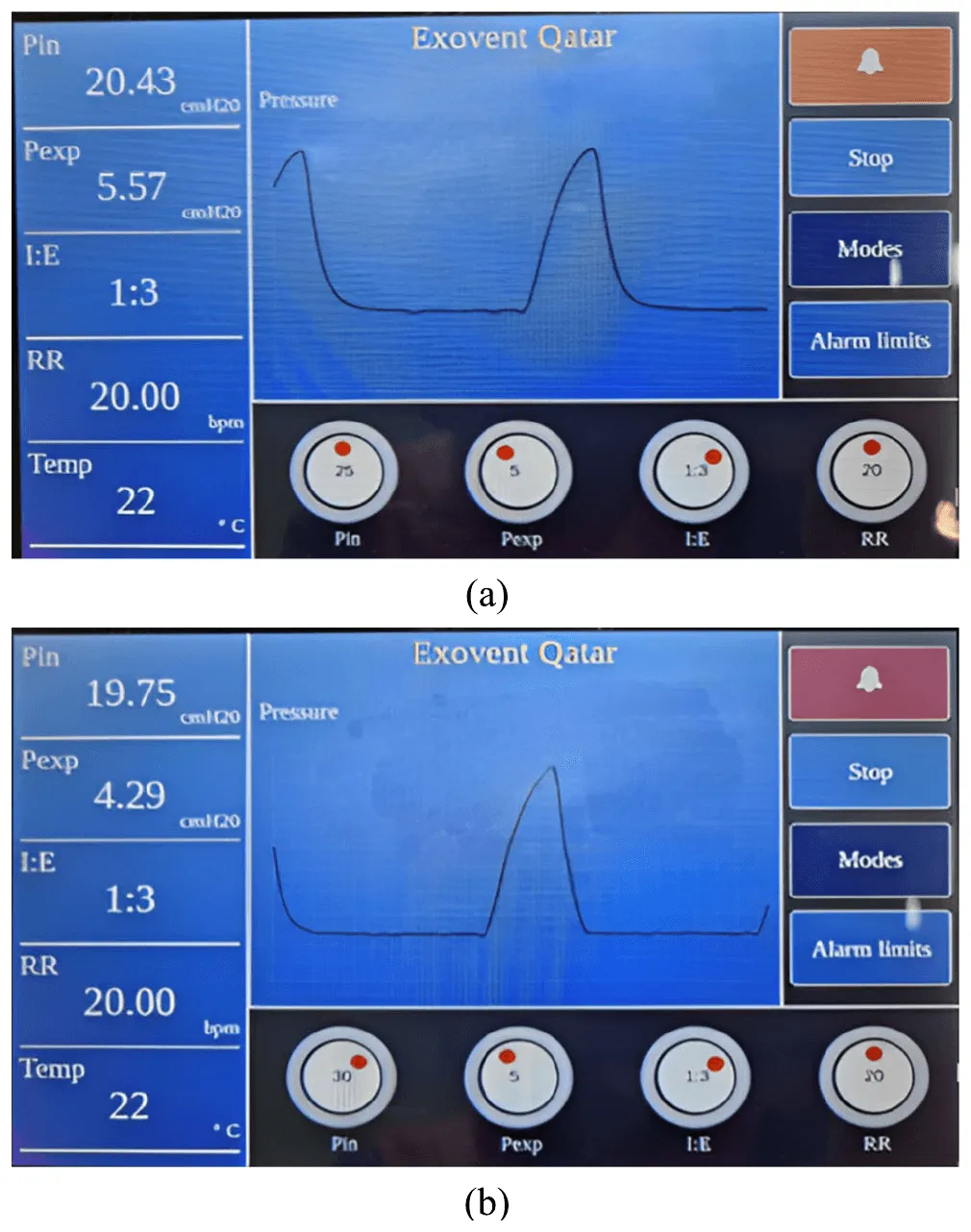
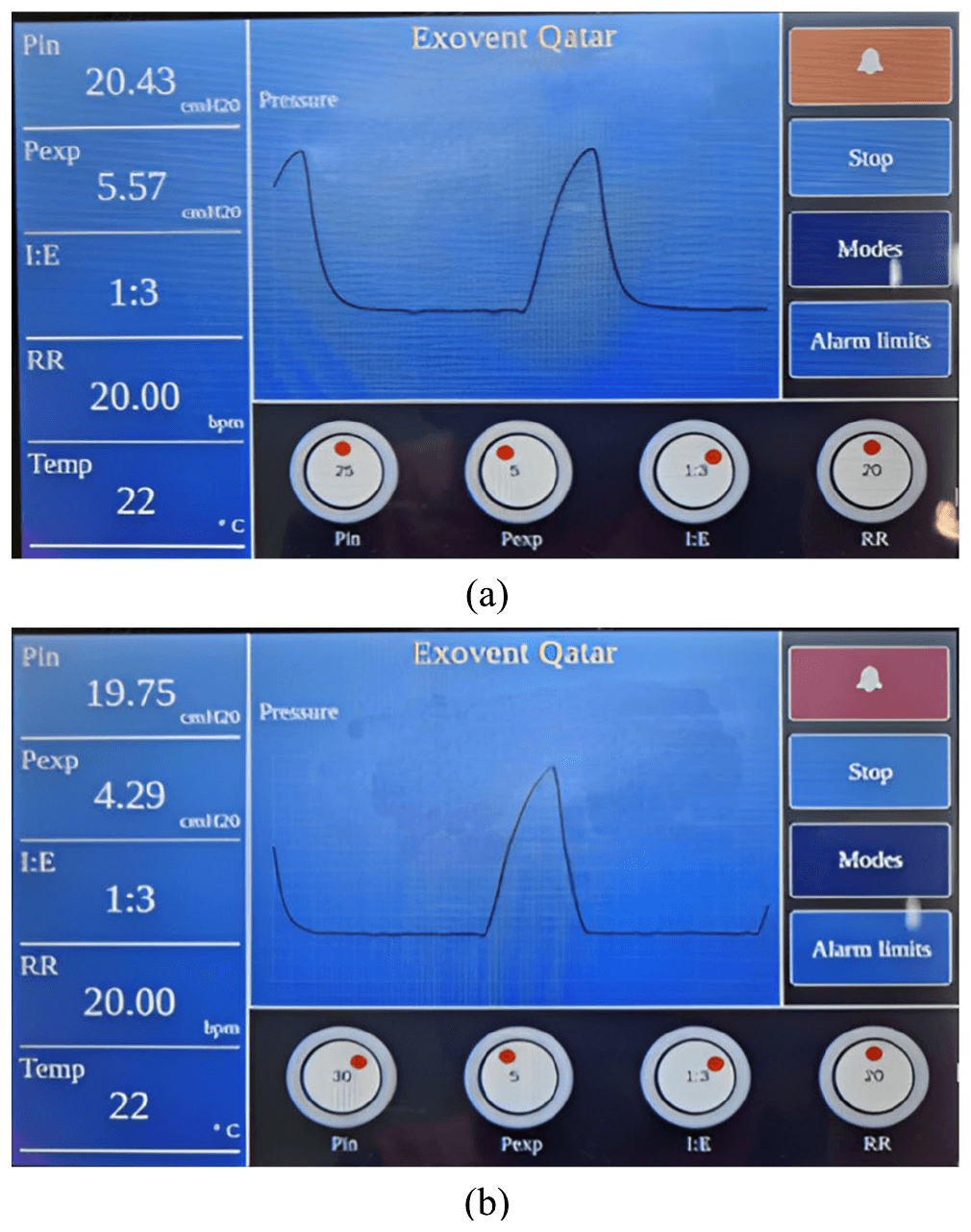
A moderate alarm turns the interface button orange when pressure deviates by about 5 units from the setting. A severe alarm, at about 10 units, turns it red and sounds a buzzer. A relay-based safety switch stops the motor if the vessel vacuum falls below 40 mbar.
- Ventilation modes tested
- 2
- Measured inspiration pressure at a 20 cmH₂O setting
- 19.66 cmH₂O
- Safety cut-off threshold
- 40 mbar
| Set pressure | Displayed pressure | |
|---|---|---|
| Cyclic inspiration | 20 cmH₂O | 19.66 cmH₂O |
| Cyclic expiration | 5 cmH₂O | 4.54 cmH₂O |
| Continuous mode | 5 cmH₂O | 4.91 cmH₂O |
| Moderate alarm test | 25 cmH₂O | 20.43 cmH₂O |
| Severe alarm test | 30 cmH₂O | 19.75 cmH₂O |
My contribution
ExoventQ was developed by a student group as their final-year BSc Electrical Engineering senior design project. I supported the project through engineering analysis, prototype evaluation and interpretation of the test results, contributed to other project tasks, and helped prepare and revise the manuscript.
Study scope
This is an engineering prototype and was not tested on people. Mannequins were used to evaluate the neck and torso seals, but their effect on vessel pressure was not examined in depth. Detailed risk analysis, long-term reliability, user training and clinical studies are needed before patient use.