Biomedical devices & simulation · 2018–2019
Low-cost ECMO cannulation simulator for clinical training
A mannequin-based training system with simulated circulation, ultrasound-compatible access pads and sensors for cannulation errors.
Qatar University and Hamad Medical Corporation · Qatar National Research Fund UREP22-003-2-001
Approach
Can a lower-cost simulator recreate the anatomy, circulation and errors that matter during ECMO cannulation training?
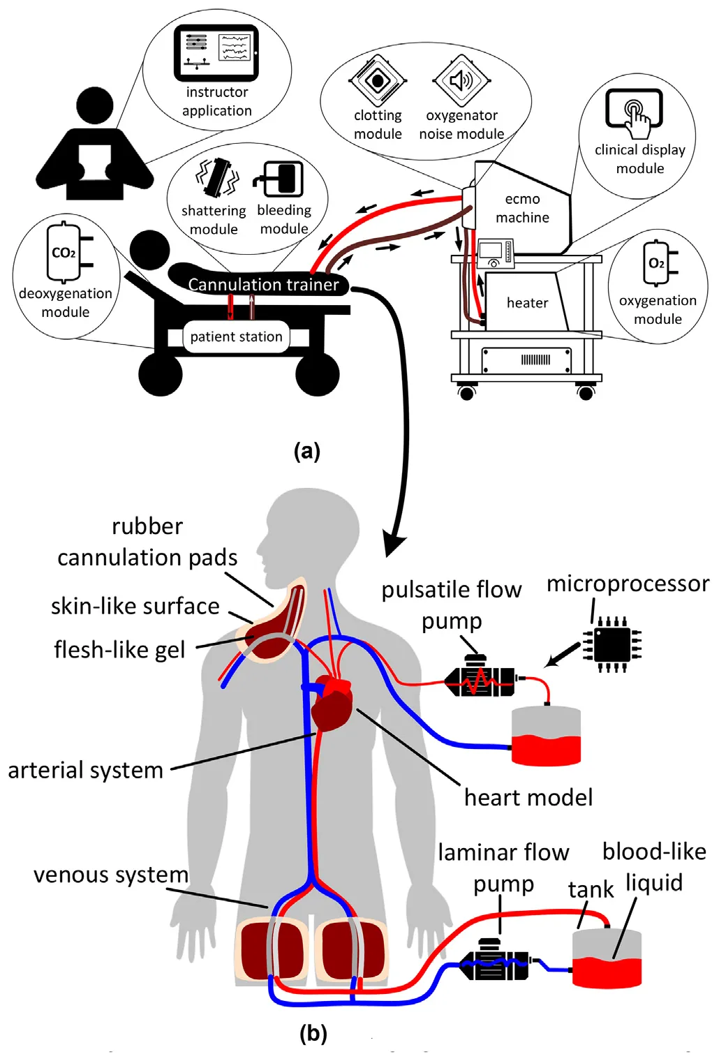
ECMO cannulation is a high-risk procedure, and many training simulators are expensive or represent only part of the circulation. Working with ECMO clinicians, the project developed a mannequin-based trainer with arterial and venous flow, ultrasound-compatible access pads and sensors that respond to procedural errors.
- Define clinical training needs
- Build pads and circulation loops
- Add sensors and test errors
Designing the trainer around clinical needs
The Egyptian Journal of Critical Care Medicine · 2018
ECMO teams must monitor many variables and respond quickly to emergencies, so hands-on training is essential. With ECMO clinicians at Hamad Medical Corporation, the team defined a lower-cost cannulation trainer to work alongside a separate ECMO machine simulator.
The design used a closed circulation system with arterial and venous networks, thermochromic blood-like fluid and silicone cannulation pads. It was planned to support guidewire insertion, vessel dilation, cannula placement and ultrasound-guided positioning, with sensors for procedural emergencies.
- Connected simulator subsystems
- 2
- ECMO configurations planned
- 3
- Cannulation approaches planned
- 3
| Design target | |
|---|---|
| ECMO configurations | VA, VV and VV-A |
| Cannulation approaches | Femoro-femoral, femoro-jugular and dual-lumen jugular |
| Circulation | Pulsatile arterial flow and laminar venous flow |
| Emergency scenarios | Flow pressure changes and cannula migration alarms |
Building the first cannulation prototype
IEEE SCOReD · 2019
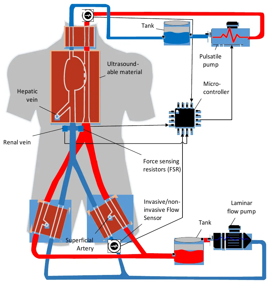
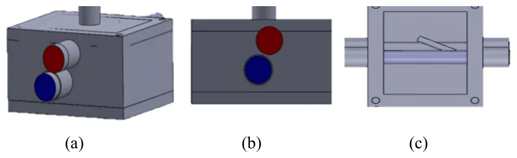
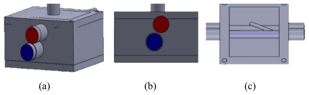
The prototype connected venous and arterial loops inside a mannequin. It included incorrect paths, such as a simulated renal vein, and ultrasound-compatible access pads based on femoral anatomy, with the artery above the larger vein and a superficial artery as a possible wrong route.
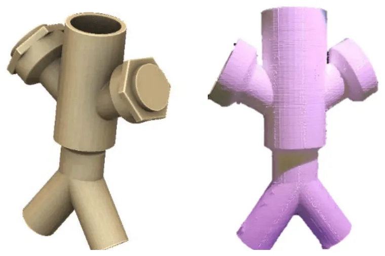
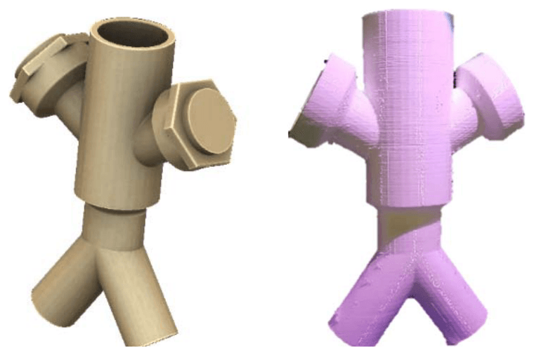
Pads were cast in designed moulds from silicone rubber, and a 3D-printed Y-connector allowed two large cannulas to meet in the venous path. A force-sensing resistor detected guidewire entry into the renal vein and triggered an LED. The team then integrated the subsystems into the mannequin and tested cannula insertion through the femoral arterial pad.
- Interconnected circulation loops
- 2
- Pad solidification time
- 2 hours
- Sensor screw angle in the Y-connector
- 60°
| Implementation | |
|---|---|
| Arterial and venous flow | Pulsatile arterial loop and laminar venous loop |
| Access training | Ultrasound-compatible, anatomically arranged silicone pads |
| Wrong-path training | Simulated renal vein and superficial artery |
| Bleeding event | Flow drop in the closed loop alerts the instructor |
| Guidewire error | Force-sensing resistor detects renal vein entry |
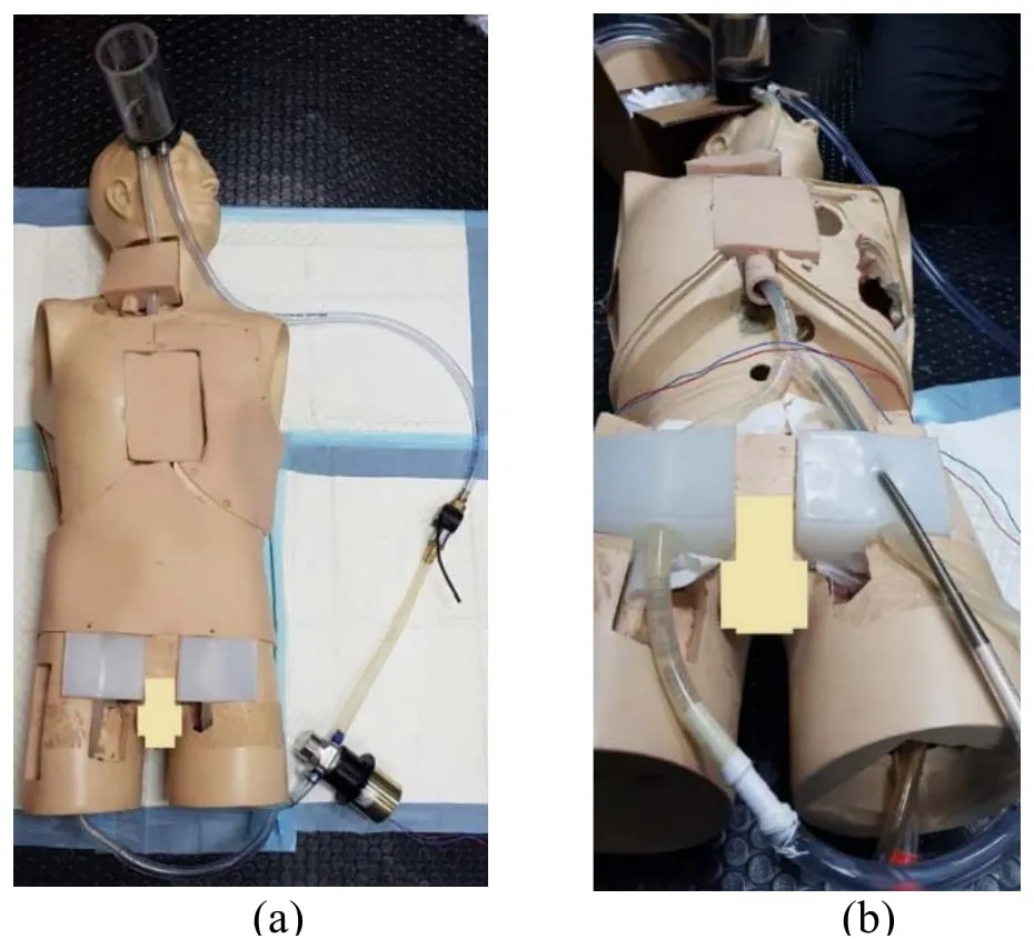
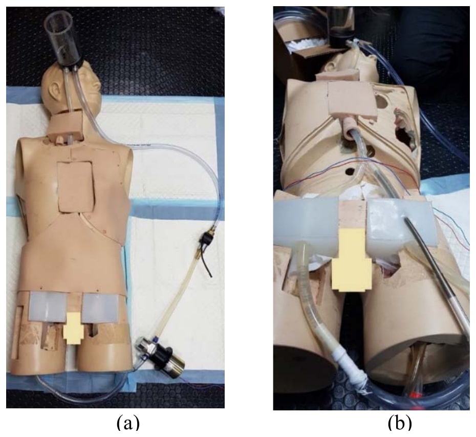
Improving anatomy, circulation and error detection
Qatar Medical Journal · 2019
The improved simulator added a closed loop linking jugular and femoral access points, with a pump and tank to regulate flow. A pump created pulsatile arterial flow, while venous flow remained laminar. The inferior vena cava junction allowed two cannulas to pass and included an alternative path representing the renal vein.
Testing focused on recalibrating the force sensor in liquid and adjusting pulsatile flow for realistic pressure. With jugular and femoral access, the simulator could support training for veno-arterial and veno-venous ECMO.
- Access regions: jugular and femoral
- 2
- ECMO training modes supported
- VA and VV
- Main prototype limitations identified
- 3
| Outcome | |
|---|---|
| Force sensor | Recalibrated in the presence of liquid |
| Pulsatile flow | Optimised for pressure realism |
| Current limitations | Tube flexibility, sensor measurement limits and rigid 3D-printing material |
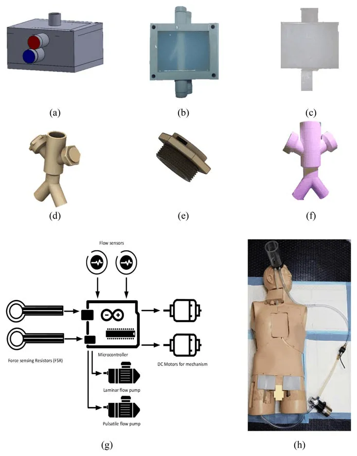
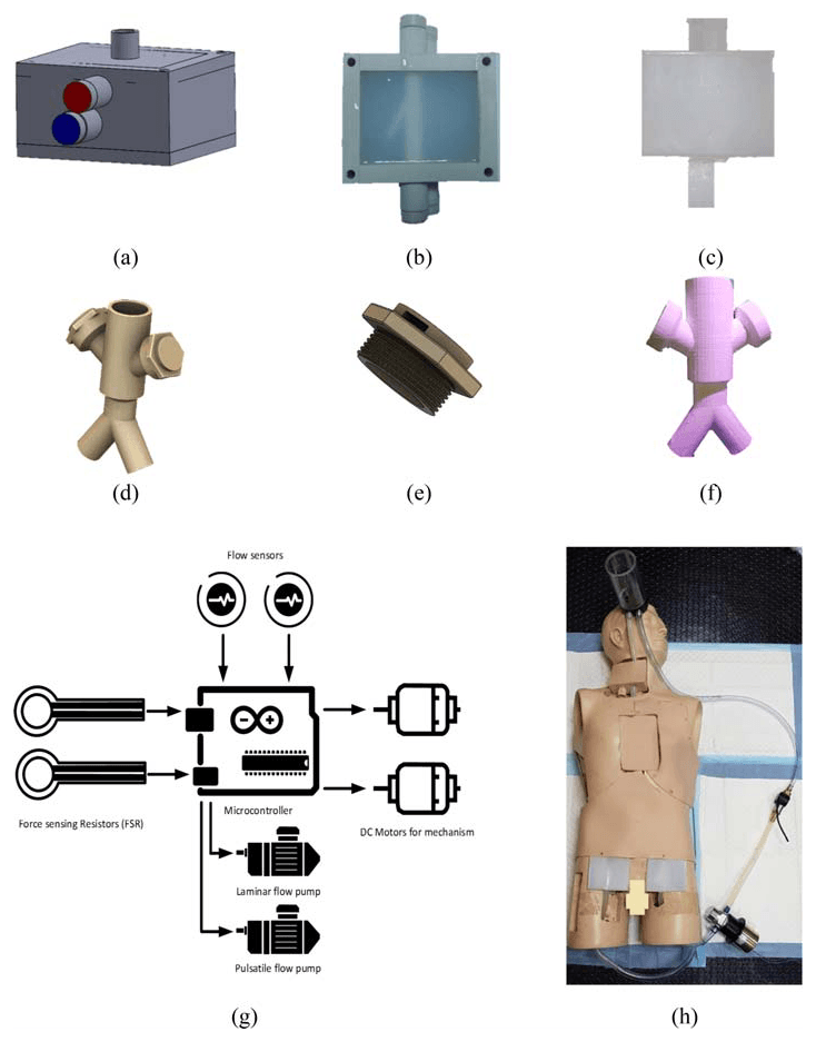
My contribution
I helped design, build and test the simulator and wrote the Arduino control code for the pump motor used to reproduce pulsatile flow. I also contributed to technical documentation and manuscript preparation, and attended hands-on ECMO training at Hamad General Hospital and Al-Wakra Hospital. The SCOReD presentation received the Best Paper Presentation Award for its presenting author, and the UREP project placed third in the 12th Annual UREP Competition in 2020.
Study scope
These papers describe simulator design and prototype testing. They do not report a formal study of trainee learning or clinical outcomes. Further testing by ECMO clinicians and improvements to tubing, sensing and printed materials were still needed.
Publications
- Preliminary Implementation of the Next Generation Cannulation Simulator2019 IEEE Student Conference on Research and Development (SCOReD) · 2019
- Towards the design and implementation of a human circulatory system for Extracorporeal Membrane Oxygenation simulationThe Egyptian Journal of Critical Care Medicine · 2018
- Towards next generation cannulation simulatorsQatar Medical Journal · 2019